Why Counters
Digital counters have become increasingly useful in many areas of modern life where number counts over a given range is crucial. They have found widespread applications in the laboratories, production lines, service centres, aerospace, military, computer, education, sports and many other areas of life.
Normally, an input clock signal of a given frequency determines the rate at which a Digital Counter operates. A display system is normally incorporated to digital counters so that the number counts can be visualised.
Design Details
For this implementation, 555 timer and 74LS192 counter IC was adopted to actualize the Digital Counter that counts from 0 to 9. The 555 timer provides the input clock signal required for the counter IC. The 555 Timer design has been featured on this blog!
The counting values are displayed using a 7 segment display. 74LS48 IC was used to decode the BCD (Binary Coded Decimal) count from the 74LS192 for display on the common cathode Seven-Segment display. You need to use 74LS47 if you are using common anode 7-segment display. The schematic of the system is presented below.
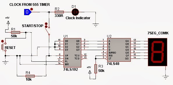
Figure: The schematic of the Digital Counter
Results
The result from the constructed system is sampled in video 1. For a better understanding of the schematic, watch video 2.
Video 1: Counter with 555 Timer input clock of 1 seconds
Video 2: 0 to 99 Counter simulation
End Note
Sets of this Digital Counter can also be cascaded further to realise a Digital Clock.
can you give me the schematic diagram of two 7 segment like in the youtube.. thats the perfect proj. that i need..
ReplyDeleteBy pausing the video, u can take the circuit diagram. The clock input which is the 555 Timer design has been featured on this blog!
DeleteThis comment has been removed by the author.
ReplyDeletehello, this is the same to my project but from 0-59 count up and if it go to 59 it will back to 0 and so on.... plz help
ReplyDeleteyou can use a NAND logic gate to trap the values of 5 and 9 at the output of the counters and then use the output of the logic gates to reset the counters.
DeleteYou may take a look at the digital clock post which implemented 0-59 count. The link is provided at the end of this blog post.
Counters are one of the many applications of sequential logic that has a widespread use from simple digital alarm clocks to computer memory pointers.
ReplyDeletePower transformers in India | Transformer Manufacturer in India
Nice Post…
ReplyDeleteThanks for sharing…
Humidity meter, Digital Counter, Conductivity Meter, Digital Timer
perfect work
ReplyDeleteNice blog very useful...
ReplyDeleteThanks for sharing...
Humidity Meter, Controller, Data Logger, Digital Counter